|
RMP
Laboratory |
RMP >
Recording Circuit |
| |
The circuit used for measuring the membrane
potential is schematized to the right. A recording electrode made of
glass (filled with 3 M KCl and with a fine chlorided silver wire inserted inside) is
lowered into a muscle cell. The voltage measured is then sent to a high
impedance pre-amplifier, and then to the recording system. This page deals
with some technical details regarding this recording setup. |
Electrodes are made of
materials which can participate in a reversible reaction with one of
the ions in the solution or electrolyte. This permits the conversion
of ionic current in solution into electron current in wires.
The most frequently used
electrode material in electrophysiology is a silver (Ag) wire coated
with a composite of Ag and silver-chloride (AgCl). The following
reaction takes place:
Cl- + Ag <-->
AgCl + e-
in a solution filled
glass micropipette.
The glass micropipette is heated and pulled to a fine tip. It is
then filled with the electrolyte solution which provides the
necessary fluid bridge between the cell and the electrode.
Very small tip diameters can minimize the electrolyte from entering
the cell and changing its normal anion and cation content; however
this is done at the expense of noise, diminishing current passing
ability and limiting recording bandwidth.
The composition of the
electrolyte depends on the type of measurement made. The
concentration of the electrolyte is also important: high electrolyte
concentrations reduces the electrode resistance, lowers voltage
noise and provides a wider recording bandwidth.
| |
Here are some questions to
think about:
Why should the microelectrode be filled with KCl as opposed to say NaCl?
What happens to the resistance of the microelectrode if the tip breaks?
if the tip is plugged? |
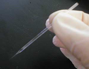
A glass micro-pipette:
note the fine tip
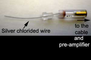
The microelectrode holder
is designed to provide an electrical coupling between the
fluid-filled glass pipette and the high input impedance
pre-amplifier. The wire fits inside the shaft of the electrode above and
the glass pipette is secured inside the holder by adjusting the
Plexiglas screw. |
|
|
|
|
|
|
|
Ions in solutions and
electrodes:
the tip potential |
|
|
The linear relation between potential
difference and current flow, as given by Ohm's law applies to aqueous
ionic solutions (cytoplasm...). However certain complications arise due
to the following problems:
The Ag/AgCl electrode performs well only in solutions containing Cl-
(see the equation above). Since current must flow in a complete
circuit: two chlorided silver electrodes are needed. If the electrodes
are immersed in two different concentrations of chloride solutions, as
they would be when one electrode is in the bathing fluid of the muscle
and the other inside the micropipette, there will be a difference in the
half-cell potentials (potential difference between the solution and the
electrode) at the two electrodes. This tip potential can be subtracted
electronically or compensated by adjusting the voltage offset. |
|
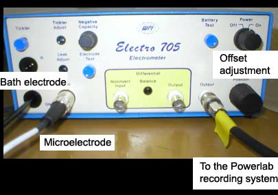
The pre-amplifier used in
the recording of membrane potential: it has connections to the bath
electrode, and the micro-electrode. The output goes to the Powerlab
recording system. The position knob adjusts the baseline to zero, when
the tip potential is recorded. |
|
|
|
High impedance
pre-amplifier |
|
|
The amplifier used is a special DC, high
resistance (>10^10 ohms) input unit. The main function of this
amplifier is to act as a resistance matching device between the
microelectrode (high resistance) and the recording system (low
resistance). The reason why this high input impedance amplifier is
needed is explained below: |
Case 1. Without the high resistance
amplifier.
Suppose that the micro-electrode (107W) is connected directly to the low
impedance ( 106W)recording system, and that Em = the membrane potential.
During the recording, current will flow through both the high resistance
of the recording electrode (Re) and the low resistance of the recording
system (Ro). Since these two resistances are in series, the total
resistance RT
is Re + Ro. |
|

|
|
The current flowing in this circuit (from V=IR)
will be: |
 |
Because the sum of the two resistances is
quite low, the current is very high. This is undesirable as it will
alter the ionic environment of the cell.
During the flow of this current, a
large fraction of
the total Em will appear as a voltage drop across the microelectrode:
and only a
small fraction of
the total voltage drop will occur across the recording system:
|
|
Since Vo is our estimate of Em, we naturally
want Vo to equal Em as closely as possible. In the case above, Vo will
be only a small fraction (< 1/10) of the actual Em, and this is
obviously undesirable. |
Case 2. With the high resistance
amplifier.
On the other hand, if the microelectrode is connected to a high
resistance (Rr = 10^10 ohms) amplifier, the situation is greatly
improved. |
|
|
|
The current flow will be
much reduced:
|

|
|
In addition, most of the
voltage drop will now occur across the amplifier, and not across
the microelectrode:
|
|
Hence, the recorded
potential will be almost identical with the actual Em. Therefore
using the high resistance amplifier has allowed us to:
1) accurately measure the
resting membrane potential
2) significantly reduce the current flowing in the circuit
Please note another
advantage of using the high resistance amplifier:
3) The sensitivity of the Em estimate (Vr) to changes in Re (if the
electrode is slightly plugged or broken) will be greatly reduced. |
|
To continue to the next section: Procedure, click here |